A closer look at the surrounding environmental changes confirms that climate change is negatively impacting our lives in every possible way. However, there is broad agreement that the approach to alleviate climate change is to attain climate neutrality.
We have to accept that for an extended period, our behaviors have enabled embodied carbon emissions from different materials to corrode the healthy, natural harmony of our environment. It seems like we are headed toward a future with more illnesses, limited resources, and increased death rates.
At the same time, we have to believe that it is not too late. With a sense of urgency and focus, we can take initiatives to become carbon neutral. Starting now with five zero goals can curtail the worst effects of climate change. These five zero goals involve zero carbon, zero energy, zero harm, zero water, and zero waste. Now, the question is: how can college campuses contribute to this target?
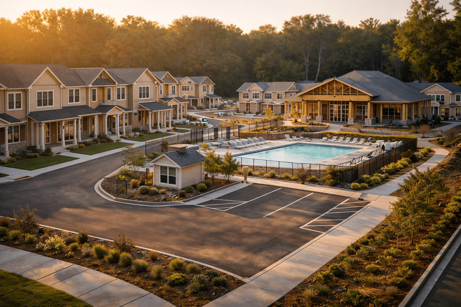
College campuses feature complex, interconnected infrastructure systems with notable potential for carbon reduction. Recent reports reveal that more than 1,100 universities worldwide have committed to decarbonization goals through climate pledges.
The Opportunity
Despite such firm stands, many educational institutions struggle to successfully execute these ambitions. It is vital to acknowledge that the untapped opportunity revolves not around aspirational targets alone, but around organized, data-based design methodologies that deal with both operational and embodied carbon concurrently.
This is the point where AEC businesses working on college campus projects can make a real difference. It is done through integrated approaches that diminish emissions, decrease lifecycle expenses, and ensure clients receive federal funding incentives.
Understandably, campus carbonization transcends installing solar panels or shifting to electric heating systems. Essentially, it calls for robust infrastructure transformation throughout all buildings and campus-wide systems. These cover MEP optimization, structural effectiveness, and material specification. Nevertheless, this complexity creates substantial value for AEC businesses equipped with the appropriate expertise and tools.
The Campus Decarbonization Landscape in American College Education
The gravity of campus decarbonization is bolstered by regulatory pressure and market demand. While in Washington State, HB 1390 mandates campus decarbonization by 2025, New York’s Regional Law 97 sets stringent emissions-reduction goals. Moreover, universities across Rhode Island, Minnesota, and Massachusetts are subject to similar state-level specifications for carbon neutrality by the end of 2050.
Don’t make the mistake of thinking of this regulatory framework as optional. In fact, it is reshaping capital planning cycles across major college campuses nationwide.
Progress until now signifies both opportunity and challenge. More interestingly, among the institutions that have achieved carbon neutrality, most have depended on carbon offsets instead of actual emissions elimination.
Goal Zero of Harvard University targets the removal of fossil fuels by 2050, with interim goals mandating 100% renewable electricity procurement by the end of 2026.
Likewise, the University of Washington Seattle manages 19 million Gross Floor Area throughout 277 buildings, with carbon neutrality planning through 2040 as compulsory infrastructure transformation.
Such examples indicate that campuses can establish ambitious targets, but execution is a whole different ballgame. It requires disciplined design choices during schematic and design creation stages. AEC firms come into the picture through superior planning, integrated coordination, and material optimization.
Curtailing Embodied Carbon in Campus Buildings
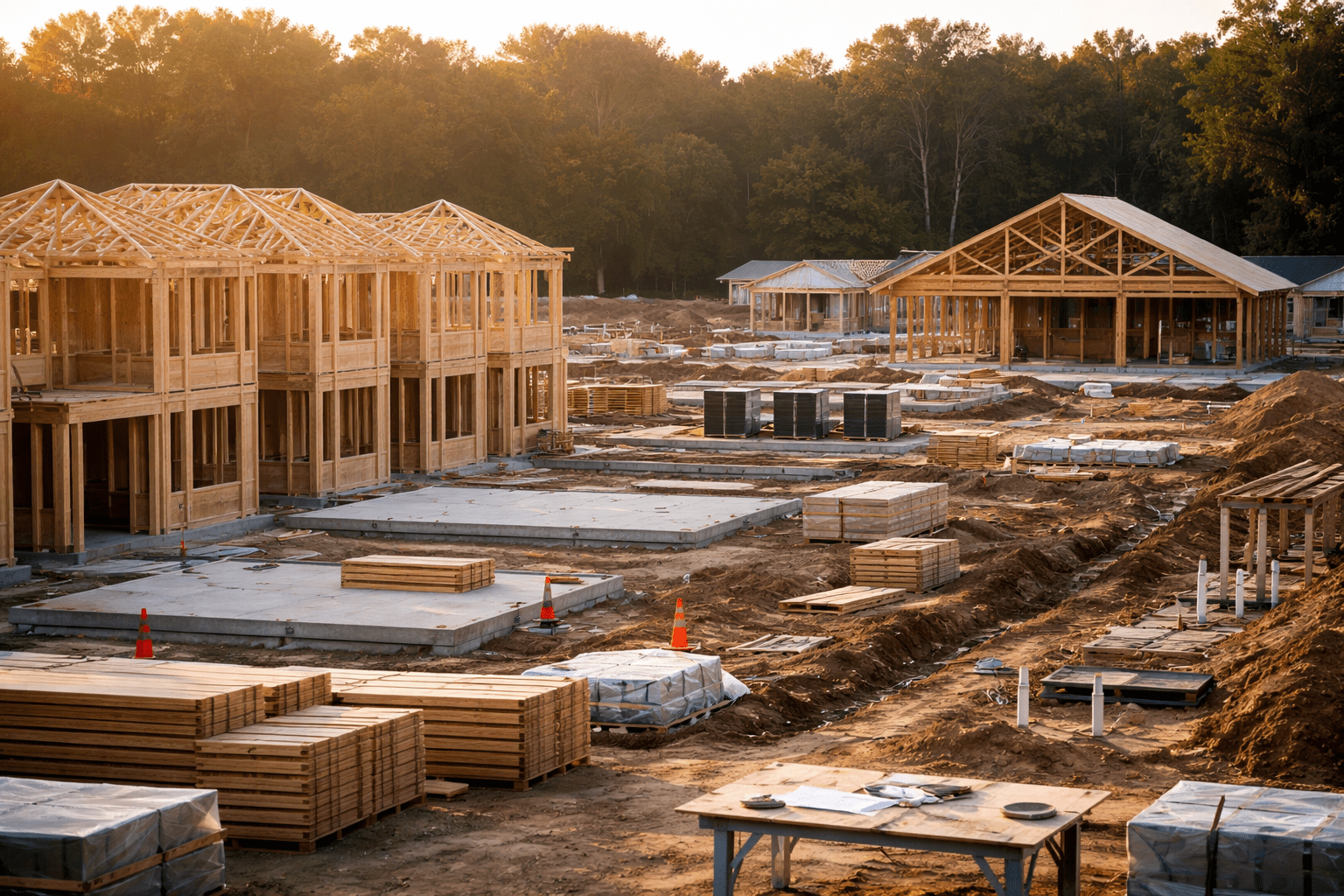
Evidently, the majority of campus decarbonization strategies emphasize operational energy. Still, embodied carbon from construction materials constitutes an increasingly large share of building lifecycle emissions. This is even more true for renovation projects. Thus, comprehending material carbon intensity is key for AEC specialists, suggesting specifications during design stages.
Keep in mind that enclosure and structural materials dominate embodied carbon profiles. Since timber has a lower carbon footprint, material selection is a quantifiable way to reduce emissions. Additionally, using Ground Granulated Blast Furnace Slag for half the cement can notably lower the concrete’s footprint.
More importantly, the most efficient approach favors structural efficacy over material substitution. Research confirms that reducing spans can cut material consumption by around 40% and embodied carbon by 35%, with concrete being more sensitive to span changes than steel. Concerning college campus projects with varied building types, this implies that AEC teams should assess structural system effectiveness early, prior to finalizing detailed specifications.
Regional Climate Zones and Energy System Design
When it comes to campus decarbonization strategies, remember that they must match local climate attributes, state-specific codes, and the energy grid composition. Hot-climate zones exhibit the greatest potential for curtailment of cooling loads. In such areas, HVAC electrification via air-source and ground-source heat pumps generates dramatic emissions reductions compared with fossil fuel-reliant systems.
On the contrary, northern climates show different design challenges. The decarbonization strategy of Middlebury College preferred heat electrification through air-source heat pumps coupled with building envelope upgrades to decrease winter peak demand. There are several other similar examples that highlight the importance of regional optimization, which can successfully bring about cost-efficient decarbonization.
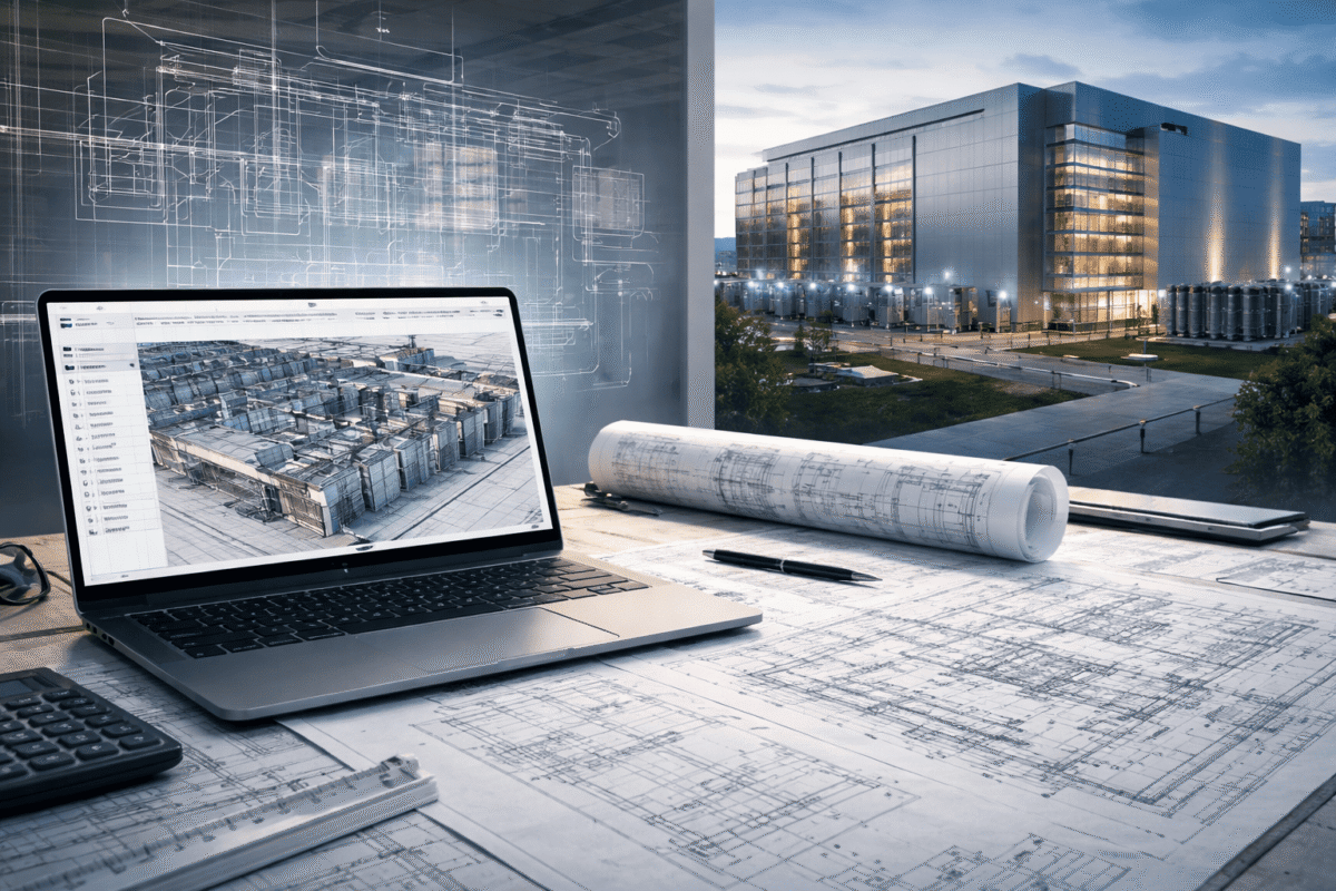
BIM as a Carbon Evaluation Platform
Integrating Building Information Modeling inherently revolutionizes embodied carbon evaluation from post-design documentation to initial-stage optimization. BIM-powered life cycle assessment takes a little over an hour. This is a drastic improvement in assessment speed compared to conventional methods, enabling iterative design exploration when modifications are cost-effective.
Besides, parametric BIM workflows facilitate AEC teams in testing material and structural alternatives instantly, which is a big plus. For instance, increasing slab depth by 150 mm to reduce material use provides real-time carbon feedback via custom schedules in Revit models.
Specifically for college campus projects, BIM models deliver three advantages. These benefits involve coordinating MEP systems for energy efficiency, deriving construction quantity takeoffs for embodied carbon evaluation, and producing construction documentation that satisfies low-carbon specifications.
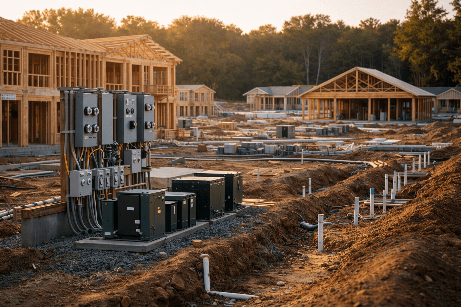
MEP Coordination Facilitating Campus Energy Electrification
Potent electrification strategies need sophisticated MEP coordination. Load calculations need to consider the peak demand of electrified systems, potentially needing campus-wide electrical infrastructure upgrades. HVAC systems should transform from chiller plants/central boilers to distributed heat pump systems or geothermal fields. This fundamentally restructures mechanical distribution networks.
Bear in mind that ideal MEP coordination during the design stage can eliminate expensive on-site modifications. Additionally, upgrading BMS, redesigning the duct for heat recovery, and displacing ventilation ought to align with architectural and structural constraints. Ultimately, coordinated BIM models enable HVAC, structural, and electrical specialists to assess interference points before construction work commences. As a result, we see a reduction in change order risk on complex campus retrofit projects.
In college campus decarbonization plans, heat recovery and thermal storage systems are becoming more and more common. Above all, they need error-free coordination among mechanical distribution, electrical capacity, and architectural layout.
Unified Design Approach for Decarbonization Success
Inevitably, cross-disciplinary integration from a project’s very beginning is mandatory for successful campus decarbonization. Accordingly, AEC professionals should prioritize evaluating structural proficiency, embodied carbon of materials, the implications of HVAC and electrical loads, and cost optimization at once.
It is evident that BIM fosters early-stage coordination among structure, architecture, MEP, and sustainability teams. Parametric analysis conducted during design helps compare structural layouts, MEP efficiency, and the use of low-carbon materials. Particularly for college campus projects, shared BIM standards ensure precise quantity takeoffs and unified energy code checks, such as IECC and ASHRAE 90.1, explicitly within the design workflow. They support turning carbon and compliance considerations into early-stage design advantages instead of late corrections.
Final Words
Clearly, college campus decarbonization is a revolutionary opportunity for AEC firms wanting to approach it systematically. While regulations are tightening, new federal incentives are currently supporting nonprofits, and institutional leaders are seeing decarbonization as a central capital planning priority.
The main opportunity lies in addressing embodied carbon, renewable energy, and building electrification at once from the beginning of design. Doing this productively calls for BIM-centric workflows, climate-specific strategies, and precise coordination across disciplines.
Uppteam’s BIM, MEP design, and structural services explicitly deal with these decarbonization imperatives. By teaming up with niche remote AEC support from Uppteam, U.S.-based AEC firms can speed up their college campus decarbonization endeavors.
Sreela Biswas