Architectural Services
Seismic Retrofitting of Legacy Infrastructure: Techniques and Modeling Workflows
-
Sreela Biswas
- November 6, 2025
- 4:17 pm
Complete Architectural Construction Document Production In Your Company Standards
Our degreed and trained architectural designers in India work as an extension of your staff on a monthly and hourly subscriptions.
Uppteam’s licensed expert MEP designers, operating remotely, collaborate with US AEC firms to deliver code-aligned MEP design solutions.
Offshore structural design experts deliver top-quality, code-compliant designs and documentation for US projects.
Seasoned civil designers remotely provide unmatched support for advancing site development, grading, and utility plans with sheer accuracy.
Cutting-edge 3D modeling and clash-coordinated documentation empower construction-ready
project delivery.
Dedicated offshore admin teams streamline architect, contractor, and engineering workflows.
Independent and guaranteed error-free model audits, clash detection, and construction
document verification by a specialized team.

U.S.-based local architectural representation, ensuring communication, accountability, and delivery expectations, managed close to the client.
Explore more
Discover our architectural design excellence through a curated selection of projects.
Explore more
Take a look at how Uppteam can elevate your projects with expert engineering solutions.
Explore more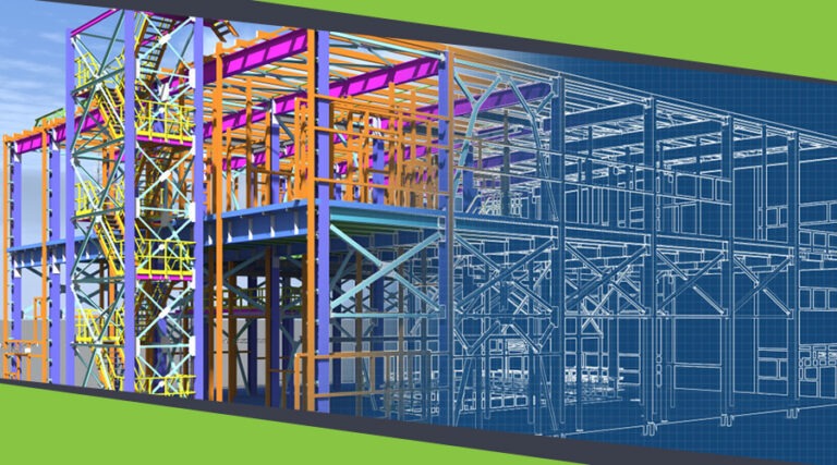
Our Structural Support Services can enhance your structural engineering projects with expert support.
Explore more
Uppteam delivers precise and reliable surveying and mapping solutions to help you make informed decisions.
Explore more
Whether you're working on residential, commercial, or industrial buildings..
Explore more
Uppteam’s Virtual Admin Support can help you with all your administrative tasks..
Explore more
Our experts work as your 3rd party quality control support partner.
Explore more
Legacy buildings, whether mid-century reinforced concrete frames, pre-code masonry warehouses, or aging steel structures, are the hidden risk in many urban portfolios. They hold cultural, operational, and financial value, but they were designed to different structural rules, materials, and loading expectations.
When an earthquake strikes, those gaps in design assumptions can become catastrophic. For AEC teams, the right retrofit strategy is not just about adding strength; it’s about choosing interventions that suit the building’s use, fabric, budget, and life-cycle goals, and proving performance through robust modeling workflows.
This article walks through practical retrofit techniques and, critically, the modeling workflows that let you choose the best solution with confidence.
Before selecting a technique, a thorough assessment is essential. That means:
Practical tip: capture a point cloud early. A precise as-built model saves time downstream in structural modeling, clash detection, and quantity takeoffs—and it’s especially valuable when retrofitting irregular or historic façades.
There’s no one-size-fits-all retrofit. Techniques fall into broad categories: global systems that change the building’s dynamic behavior, local strengthening of members/joints, and energy-dissipating additions. Below are commonly used strategies with practical pros/cons.
Base isolation: inserts bearings or pads (lead rubber bearings, friction pendulum bearings) between foundation and superstructure to decouple seismic energy. Highly effective for reducing drift and base shear, especially for critical facilities. Best for buildings where functional continuity is crucial and foundations are accessible for intervention.
Full-frame ductility upgrade: upgrading column-beam connections and adding continuous load paths to allow plastic rotation in controlled locations.
When to use: critical infrastructure, cultural buildings needing minimal superstructure damage, or where downtime costs outweigh retrofit installation costs.
Viscous or hysteretic dampers can be added to frames or braced bays to absorb seismic energy and reduce accelerations and interstory drift.
Tuned mass dampers are more common for wind but can be effective for long-period structures.
When to use: buildings where adding stiffness is infeasible due to architectural constraints, but adding devices in select bays is possible.
Fiber-Reinforced Polymer (FRP) wrapping: excellent for columns and beams to increase shear and flexural capacity with minimal section enlargement.
Concrete jacketing and steel jacketing: increase cross-sectional area and confinement; ideal where access and added weight are acceptable.
Masonry retrofits: bed joint reinforcement, shotcrete, or cavity tying for unreinforced masonry.
When to use: targeted weakness (columns, beam-column joints, infills) and when architectural preservation is a concern.
Soil improvement or underpinning, combined with base isolation or pile retrofits, can address liquefaction and foundation instability.
Choosing among these depends on performance targets, cost, constructability, and desired downtime. Comparative studies show base isolation offers large reductions in interstory drift and base shear, while FRP and dampers provide cost-effective localized improvements.
A good retrofit is a design validated by analysis. The modeling workflow below is pragmatic for AEC teams and partners who provide modeling, analysis, and documentation support.
Import LiDAR point clouds or photogrammetric meshes into Revit/Archicad and create a federated BIM. Ensure structural members are modeled to reflect existing sizes, connectivity, and material properties.
Tag observed damage and uncertainty zones (e.g., unknown reinforcement details) as model metadata.
Here’s where having accurate as-built data pays off fast. Converting point clouds into clean structural models is tedious work, but it’s also the foundation for everything else. Some firms handle this in-house; others work with modeling specialists who can turn around a Revit model in days instead of weeks. Either way, don’t skip this step or try to shortcut it with assumptions.
Run quick hand calculations and linear static checks (equivalent lateral force) to flag gross deficiencies.
Perform demand/capacity ratios for columns, beams, and critical joints to prioritize interventions.
Use pushover analysis to identify hinge formation patterns and weak stories. This provides a performance point estimate and helps compare the relative benefits of adding shear walls, dampers, or jacketing.
Create performance objectives aligned to owner needs: life safety, immediate occupancy, or collapse prevention.
For high-importance structures or when proposing base isolation/energy devices, use NLTH with suites of ground motions scaled to the target spectrum. NLTH captures dynamic effects, higher-mode contributions, and the interaction between devices and structure—critical for quantifying expected drifts and forces under realistic excitations. Recent practice increasingly demands NLTH for complex retrofits and critical infrastructure projects.
If foundation upgrades or base isolation are on the table, include SSI modeling and check for uplift, bearing failure, and pile-liquefaction interactions.
Model the sequence of work to verify load paths during partial demolition or temporary supports. This step is often overlooked but essential to avoid inadvertent overloads during retrofitting.
Produce coordinated construction drawings, schedules, and BIM-federated 3D views for site teams. Consider embedded sensors and structural health monitoring (strain gauges and accelerometers), and create a digital twin for long-term performance tracking.
Here are three scenarios we see come up again and again:
A 1960s concrete office tower: The building had good bones, but the LiDAR scan and subsequent Revit model revealed what the drawings didn’t show—a soft story at ground level where the lobby opened up. Pushover analysis confirmed it: that floor would concentrate all the drift and likely fail in a moderate quake. The fix was adding reinforced concrete shear walls in the core, plus some strategic FRP wrapping on columns that couldn’t be easily enlarged. Time-history analysis showed that the building would now meet Life Safety performance requirements. Total downtime: eight weeks. The owner could live with that because the alternative—months of vacancy or catastrophic failure—was far worse.
An old masonry school building: This one had heritage constraints, so heavy-handed fixes were off the table. Condition surveys and mortar testing indicated the need for bed-joint reinforcement and a carefully applied knit-mesh shotcrete system to preserve the exterior character. The dynamic analysis showed a real improvement in damping, and the team installed monitoring equipment during the monsoon season to track any settlement issues. It wasn’t sexy work, but it kept a community landmark standing and safe for another generation of students.
A hospital that couldn’t shut down: Base isolation for the critical-care wings, viscous dampers for the adjacent blocks. The soil-structure interaction model guided bearing selection due to the site’s mixed soil conditions. Everything had to be phased so patient care never stopped, which meant the temporary load path analysis was just as critical as the final design. Get that wrong, and you’re not just risking the building—you’re risking lives in real time.
Retrofit projects eat up modeling hours. Between as-built capture, multiple analysis runs, sensitivity studies, and coordinated documentation, the workload can swamp a small team or pull senior engineers away from the design decisions that actually need their judgment.
That’s why many firms lean on outside modeling support—not because they can’t do the work, but because outsourcing the grunt work lets them stay focused on client strategy and technical problem-solving. A good modeling partner can take your point cloud and turn it into an analysis-ready BIM. They can set up and run your ETABS or OpenSees models, batch-process time-history analyses for different retrofit scenarios, and generate the coordinated CD sets and demo drawings you need for permits and construction.
Uppteam does exactly this kind of work. We handle the modeling, the documentation, the QC checks—basically the repeatable, process-driven tasks that don’t require a PE stamp but do require accuracy and speed. Think of it as an extension of your team that scales up when you need it and doesn’t add to overhead when you don’t. Whether it’s one heritage building or a portfolio-wide seismic program, we keep the modeling side moving so your engineers can keep designing.
Choose retrofits with life-cycle outcomes in mind. Sometimes a lower-cost local strengthening makes sense for short-term occupancy goals; in other cases, the greater upfront cost of base isolation is justified by drastically reduced downtime and repair costs after a major event. Combine financial modeling with expected performance (probabilistic risk assessment) to present owners with transparent tradeoffs. Recent research also highlights the environmental benefits of targeted retrofits over full replacements when the carbon footprint is considered.
Retrofitting isn’t glamorous work, but it matters. These buildings aren’t going anywhere—they’re too valuable, too embedded in their communities, too expensive to replace. The question is whether they’ll survive the next earthquake or become another news story about preventable failure.
The firms doing this well aren’t necessarily the biggest. They’re the ones who know how to get accurate data, run the right analyses, and coordinate across disciplines without letting the project bog down in endless revisions. And when the modeling workload threatens to derail the schedule, they know when to call in help.
If you’re staring down a seismic retrofit project and wondering how you’ll fit the modeling work into an already packed schedule, let’s talk. Uppteam can take that piece off your plate—point cloud to construction documents, analysis support to QC—so your team can focus on what you do best: solving problems and keeping clients happy.
Your One-Stop MEP Design Support Solution is Here
Hire Remote Team at an Affordable Price!