


Our Structural Support Services can enhance your structural engineering projects with expert support. From conceptual design to detailed drawings, our experienced team provides end-to-end structural solutions across commercial, multi-family, industrial, retail, and residential projects. Learn how we can support your firm’s productivity with high-quality, fast turnarounds and exceptional attention to detail. Download the brochure to explore how we can bring your next project to life!
Structural Design Support
Structural Engineering Design Support for a Single-Story Residential Renovation and Addition in Florida
-
Sreela Biswas
- December 31, 2025
- 1:17 pm
Task Assigned
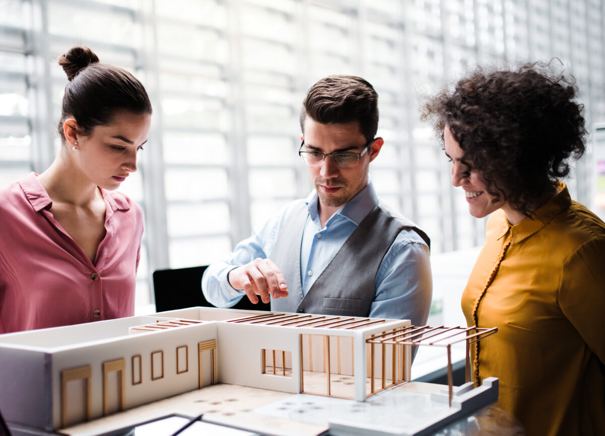
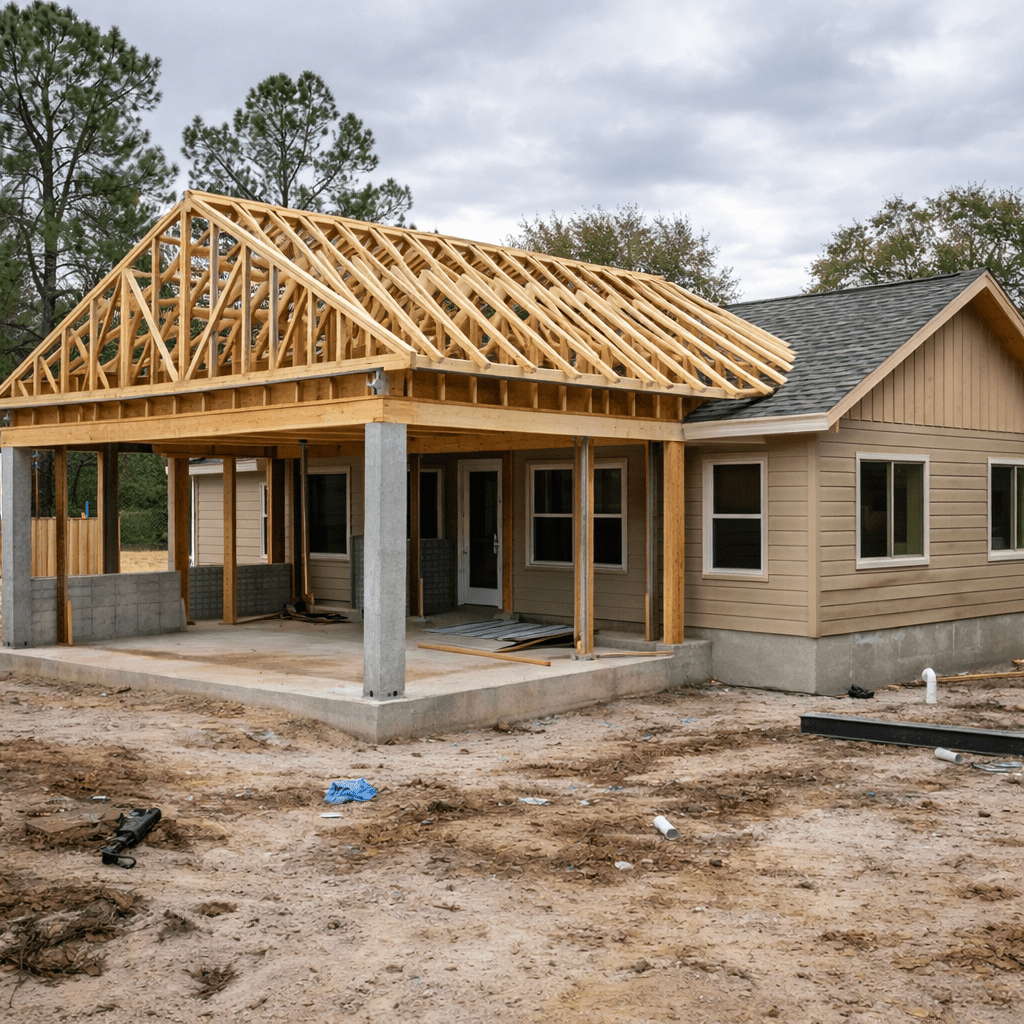
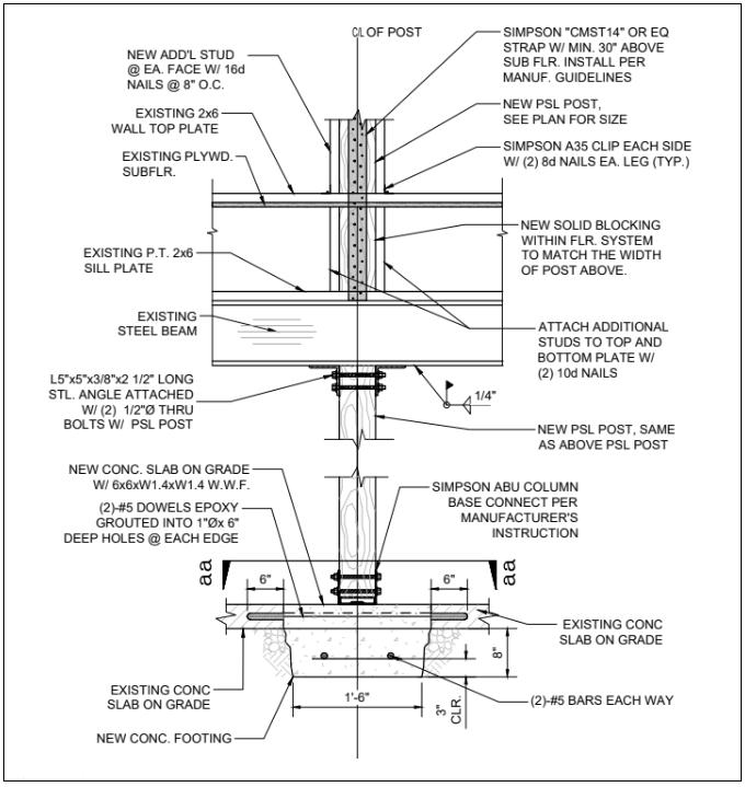
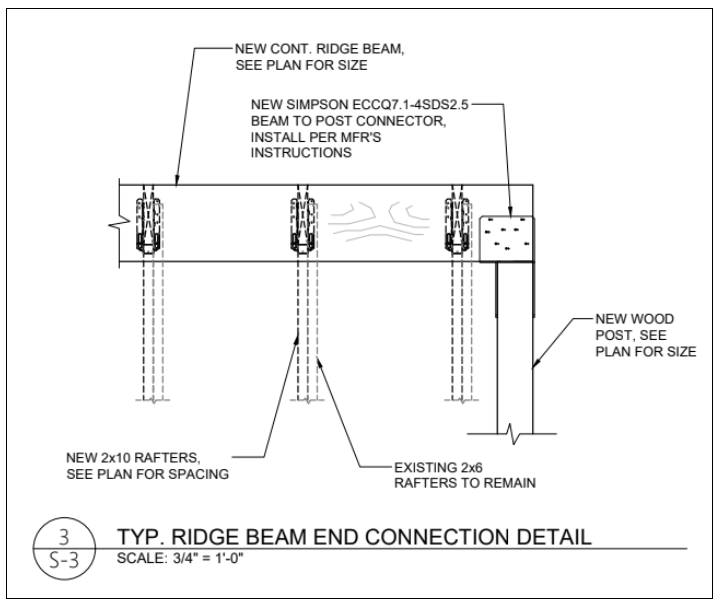
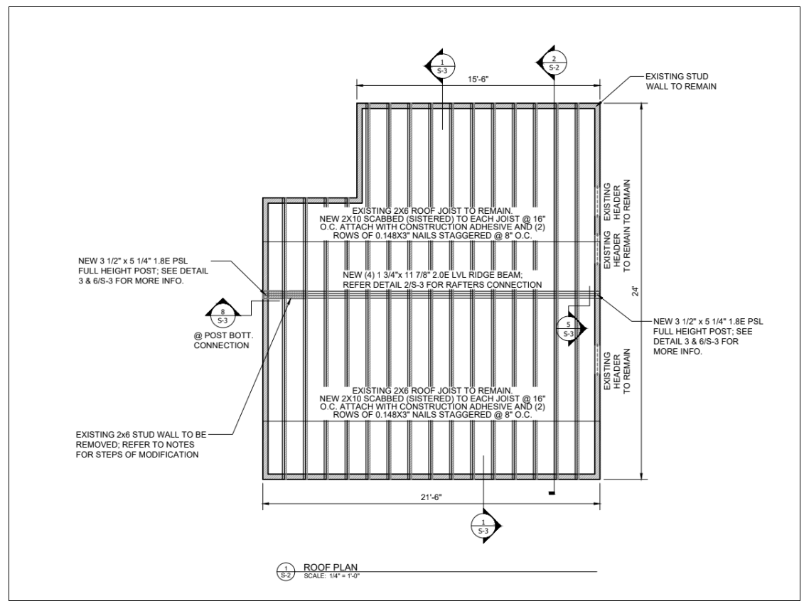
Uppteam was involved in a project to deliver remote structural engineering design support for a prevailing single-story building, along with a new residential addition. The scope of this project emphasized supporting the structural specifications for the expansion. Another key aspect of the project was to integrate the structural requirements with the existing structure. Our team’s responsibilities comprised the structural design and detailing of beams, walls, and columns necessary for the renovation and new addition of the prefabricated roof trusses.
Project Timeline
- Phase 1 - The first phase consisted of developing the structural design of roof connectors, walls, beams, and columns for the renovation and new addition to the existing infrastructure
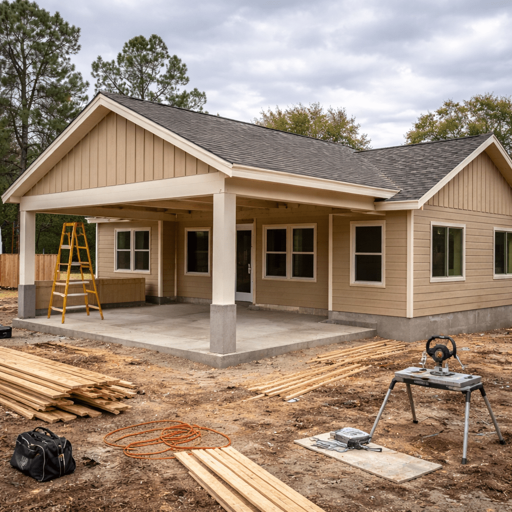
- Phase 2 - In this phase, our team prepared structural drawings and construction-ready details.
- Phase 3 - The task in the final phase was to model coordination and documentation management within the Revit 360 platform.
Additional Notes
- This project’s scope was quite straightforward because of its residential nature. However, delivering the project within the stipulated time was the main challenge. The project was handled by a competent internal team using Revit 360 workflows.
- To deal with the project-related tasks, we established tailored project standards within the Revit 360 environment, accessed through ACC, to simplify coordination and documentation. Essential 2D structural details were also generated and uploaded into the CMS system, enabling effective reuse in future residential projects.
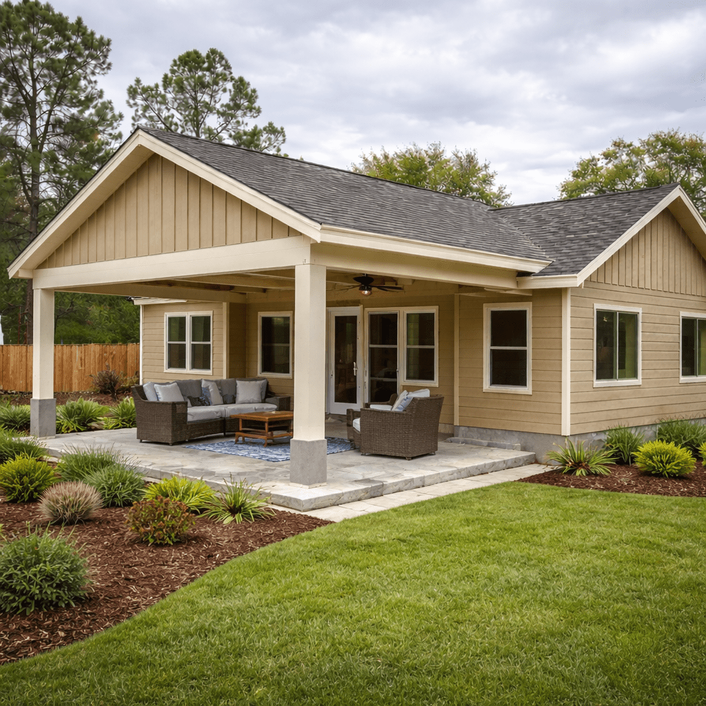
- Uppteam delivered the project successfully on time. In addition to satisfying immediate project needs, this project led to the creation of a reusable BIM workflow for subsequent residential engagements.
Civil
Urban Heat Resilience: Structural and Civil Design Tactics for Cooler Cities
-
- December 25, 2025
- 12:28 pm
Structural Design Support
Structural Modeling for a Residential Building in Brooklyn, New York
-
- November 26, 2025
- 10:43 am
Task Assigned
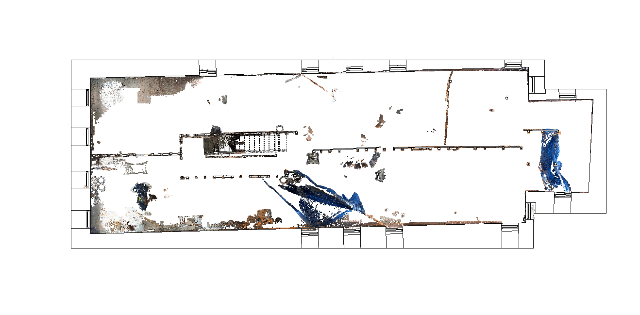
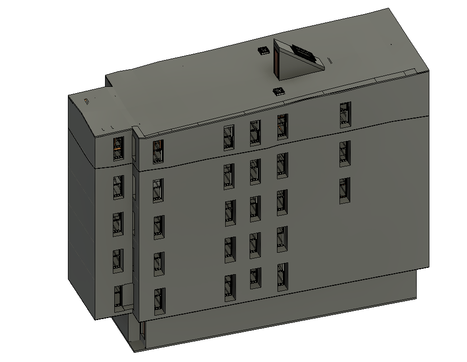
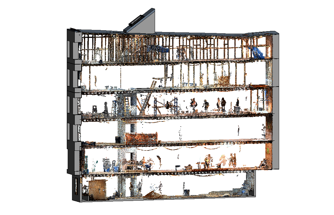
Uppteam was engaged to deliver structural and architectural BIM modeling for the interior renovation of a multi-family residential building at Willow Street in Brooklyn, New York. The project required developing a highly accurate Revit model at LOD 350, based on point cloud data, to support detailed design, coordination, and future documentation needs. The focus was solely on interior spaces, ensuring precise capture of existing conditions for future project teams.
Project Timeline
- Phase 1 - Data Review & Modeling Strategy: Assessed point cloud files, confirmed modeling requirements, and established an approach for representing non-orthogonal existing conditions.
- Phase 2 – BIM Model Development & Submission: Developed the interior architectural and structural model at LOD 350, aligned it with verified point cloud geometry, and delivered the final Revit model for client review and use.
Additional Notes
- The existing building was fully non-orthogonal, requiring clarification on modeling expectations. After confirming with the client, Uppteam modeled the structure using the point cloud rather than defaulting to orthogonal geometry, ensuring accurate representation of inclinations and structural deviations.
- The client received a highly accurate, coordination-ready BIM model that precisely reflects real site conditions, reducing future design conflicts and improving project planning efficiency.
Structural Design Support
Handing Over BIM-Ready SHM (Structural Health Monitoring) Systems
-
- November 14, 2025
- 10:34 am

Structural Design Support
Off-Site & Modular: Structural Detailing That Bridges Design and Fabrication
-
- November 12, 2025
- 12:43 pm
Structural Design Support
Structural Design and Drafting for Vaulted Ceiling Renovation – Georgia, USA
-
- November 11, 2025
- 1:35 pm
Task Assigned
Uppteam was engaged to provide structural design and drafting services for the renovation of a vaulted ceiling in Georgia, USA. The project involved partial demolition and construction of a new ceiling while preserving architectural intent and structural integrity. The scope included roof framing plans, detailing connections, and coordination with the site team to ensure load distribution and stability during the transition.
Project Timeline
- Phase 1 - Assessment & Demolition Planning: Conducted a detailed assessment of the existing vaulted ceiling, identified areas for partial demolition, and developed a roof layout that minimized disruption to the existing structure.
- Phase 2 – Structural Design & Documentation: Designed the new vaulted ceiling framing system, finalized all structural details, and prepared construction drawings. Coordination with the client and site team ensured alignment with existing conditions and seamless execution.
Additional Notes
- The existing vaulted ceiling required partial demolition without compromising the stability of the surrounding structure. So, the team carefully planned the demolition sequence and introduced structural reinforcements where necessary.
- Our team also closely coordinated with the client and site engineers, ensuring that all new members were accurately placed and integrated with the existing framework.
- The vaulted ceiling renovation was completed successfully with a robust, structurally sound system that aligned with the architectural vision. Uppteam’s detailed planning, precise documentation, and coordination ensured smooth on-site implementation and long-term structural performance.
Structural Design Support
How Structural Teams Are Rethinking Stormwater Integration for Resilient Urban Infrastructure
-
- November 11, 2025
- 6:31 am
Structural Design Support
Embodied Carbon for Structural Design: Practical Steps, Hard Decisions & Simple Decision Matrix
-
- November 4, 2025
- 11:21 am

Structural Design Support
Embodied Carbon in Structural Design: Proven Strategies to Lower Your Project’s Footprint
-
- October 27, 2025
- 7:32 am